Floor Plan Cut Plane Height

2 Kanal Classial House Plan With Center Double Height Stair House Plans Home Design Plans Front Elevation Designs

26 X 40 Cape House Plans Second Units Rental Guest House Vacation Home 20x40 2 Bedroom 2 Tin Square House Plans 20x40 House Plans Small Floor Plans
Custom Floor Plan Cut Plane Height By View Cad Tips

Pin By Mel Loyola Agosto On Construction Details How To Plan Interior Rendering Restaurant Design

Gallery Of Silence House First Design Studio 31 One Design Design Design Studio

Kitchen Floor Plan No Island Which Helps For Aging In Place And Universal Design Plan For The Future Of Your Cl Kitchen Floor Plans Floor Plans Kitchen Plans
These 3 planes define the primary range of the view range.
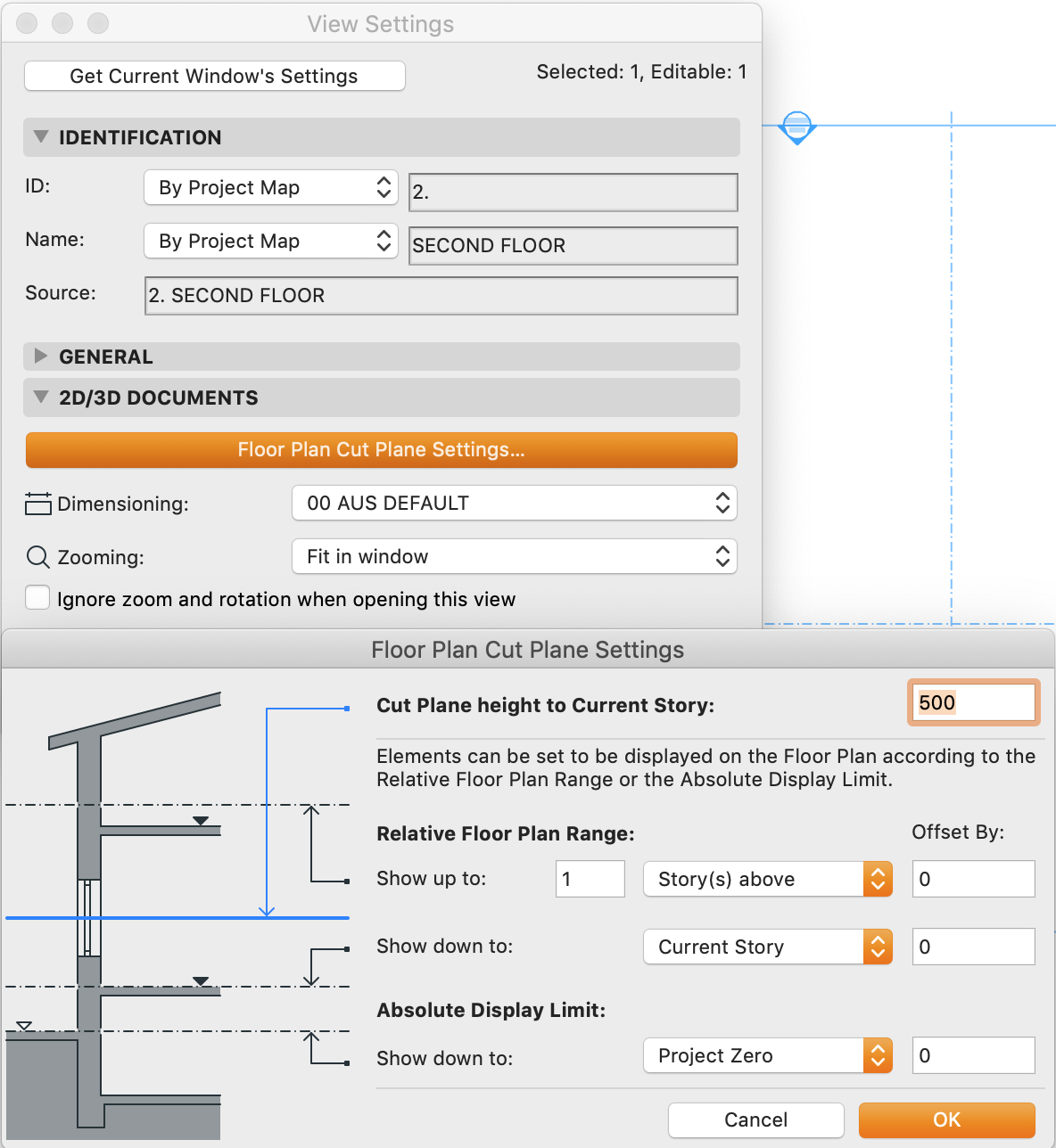
Floor plan cut plane height. But when you open the floor plan you can t see the windows. Use document floor plan cut plane to open the floor plan cut plane settings dialog box. Use the depth clipping parameter to display parts of a model below the cut plane. The reason why we can t see it is that they are placed above the cut plane of the plan s view range.
The other options in this dialog box relative floor plan range and. The generic model family category will appear in the floor plan view. It is also called a plan which is a measured plane typically projected at the floor height of 4 ft 1 2 m as opposed to an elevation which is a measured plane projected from the side of a building along its height or a section or cross section where a building is cut along an axis to reveal the interior structure. View depth is an additional plane outside of the primary range.
The back clip plane is defined by the view depth parameter which is. You can set the level of view depth to show elements below the bottom clip plane. About the view range. Use document floor plan cut plane to open the floor plan cut plane settings dialog box.
The cut plane is a plane that determines at what height certain elements in the view are shown cut. You activate this feature using the depth clipping parameter for the plan view. The floor plan cut the model at elevation 1200 mm but the windows sill height are at 1700 mm. If you only want the wall visible in the plan view as it appears in the view range of level 3 you can clip the wall from view using the depth clipping parameter.
If the family category is changed lighting fixtures the family will not be visible in the floor plan view. Cut plane height to current story enter the height at which elements will be cut for display on the floor plan.

045cort Ffplan Jpg Casas Proyectos Presentaciones

Floor Plans Construction Drawings Northern Architecture

Example Image Office Layout Plan Office Layout Plan Office Layout Office Floor Plan

30x40 Barndominium Floor Plans Barndominium Floor Plans 30x40 House Plans House Floor Plans

16x36 House 16x36h9i 744 Sq Ft Excellent Floor Plans Tiny House Floor Plans Carriage House Plans Cabin Floor Plans

Pin By Sohail Raza On House Plane 20x40 House Plans 2bhk House Plan Indian House Plans

14x40 Cabin Floor Plans Cabin Floor Plans One Bedroom House Plans Cabin Floor
How To Read A Floor Plan With Dimensions Houseplans Blog Houseplans Com
14 Beginner Tips To Create A Floor Plan In Revit Revit Pure

View Range Revit Products Floor Plans Revit Architecture Revit Tutorial

1st Floor 27 42 House Plan Duplex House Plans House Plans Indian House Plans

Floor Plan Cut Plane Global Setting

35 Ft X 20 Ft Floor Plans Click To View Print Two Bedroom Floor Plan Cottage House Plans Bedroom Floor Plans

Garage W 2nd Floor Apartment Apartment Floor Plans Garage House Plans Apartment Plans

Pin On Moving Home

Modern Style House Plan 2 Beds 2 Baths 991 Sq Ft Plan 933 5 Modern Style House Plans Small House Plans Bedroom House Plans

Must Know Modern Homes Gropius House Modern Floor Plans Floor Plans Walter Gropius

16x16 Duplex 581 Sq Ft Pdf Floor Plan Instant Download Model 23a Floor Plans Small Floor Plans Roof Framing
3

Hpm Home Plans Home Plan 001 2270 In 2020 House Plans How To Plan Floor Plans

Spatial Definition By Height To Width Ratio Spatial Design Concept

560 Ft 20 X 28 House Plan Tiny House Plans Tiny House Floor Plans Small House Plans

Floor Plan Upstairs Architecture Architecture Library Floor Plan Floor Plan Design Floor Plans

3 Storey Home Plans Splendid House Fresh In Ideas House Design Pictures House Plans With Pictures Two Story House Design

Pin On Ab

Kitchen Wall Elevation Google Search One Wall Kitchen Kitchen Layout Plans Kitchen Elevation

Floor Plan Cut Plane Settings Youtube

25x30 House Plan Elevation 3d View 3d Elevation House Elevation Glory Architecture 20x30 House Plans 2bhk House Plan 30x40 House Plans

Offering The Best Deal On Quality Condominiums In New Jersey S Hottest Real Estate Markets Two Bedroom House Bedroom Floor Plans Two Bedroom Floor Plan

Pin On Floorplan

Plan 730002mrk Exclusive 2 Story Craftsman House Plan With Symmetrical Front Elevation In 2020 Craftsman House Craftsman House Plan Dream House Plans

Pin On Architect Plan

The Difference Between Site Plan Vs Floor Plan

One Room Home Addition Plans Bing Images Room Addition Plans Home Addition Plans Bedroom Addition Plans

12x12 House W Loft 12x12h1 268 Sq Ft Excellent Floor Plans Tiny House Floor Plans House Plan With Loft Tiny Houses Plans With Loft

Pin On House Plans 4 Bedroom

33 Awesome Duplex House Plans For 20x30 Site Images 20x30 House Plans Duplex House Plans Guest House Plans

General And Cosmetic Dentistry 1 974 Sq Ft Medical Office Design Clinic Design Dentist Office Design

122 Studio Before And After Photos Studio Floor Plans Studio Layout Pottery Studio

Single Wide Mobile Home Floor Plans 2 Bedroom

3 Bedroom Floor Plan 14m X 7m 100sqm Small And Minimalist House Floor Plans One Floor House Plans House Flooring

Small Church Floor Plan Designs Home Design Church Building Design Church Design Architecture Church Building Plans

